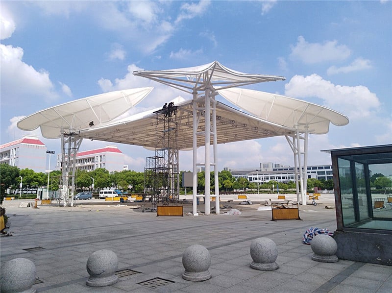
Rain is not an exception—it is a design premise. For membrane structure buildings, especially tensile membrane canopies, drainage performance directly determines long-term safety, aesthetics, and service life.
From Jutent engineering practice, most membrane failures are not caused by material strength, but by improper drainage geometry and insufficient membrane pretension. Drainage must be integrated into the structural logic from the earliest design stage.
Key Takeaways
- Drainage slope, curvature, and membrane pretension must function as a unified system
- Textile architecture requires steeper slopes than conventional rigid roofs
- Water accumulation on membranes follows a “Matthew Effect”
- Drainage components must be structurally coordinated with membrane nodes
- Drainage strategy should be selected based on project scale and openness
Drainage Starts with Geometry, Not Pipes
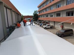
In membrane structure buildings, drainage depends primarily on surface geometry rather than mechanical systems. The drainage slope and outlet positions must be determined based on building function, plan layout, and boundary constraints.
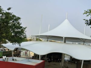
For canopy architecture, continuous and uninterrupted water flow across the membrane surface is critical. In regions with heavy rainfall or snow loads, larger membrane gradients and additional snow protection measures are required.
Slope Requirements for Textile Architecture
Compared with traditional buildings, textile membrane roofs demand significantly higher drainage slopes due to their flexible nature and sensitivity to deformation under load.
| Membrane Area Type | Recommended Drainage Requirement | Engineering Purpose |
|---|---|---|
| Flat membrane areas | ≥ 15% – 20% slope | Ensures rapid water runoff and minimizes ponding risk |
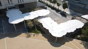
| Hyperbolic membrane ridges | ≥ 10% slope | Maintains directional drainage along curvature |
| Membrane pretension | 1.0 – 2.0 kN/m | Limits deformation under rainwater loading |
The “Matthew Effect” of Water Accumulation
Water accumulation on membrane surfaces exhibits a clear Matthew Effect: once a local depression forms, more water flows into that area, increasing deformation and accelerating structural risk.
To prevent this chain reaction, sufficient slope, continuous curvature, and stable pretension distribution must be designed together as an integrated system.
Organized vs. Unorganized Drainage Strategies
Due to the free-form nature of membrane structures, drainage design must be planned simultaneously with architectural modeling. Two main drainage approaches are commonly used.
- Unorganized drainage: Free edge runoff, suitable for small and open structures
- Organized drainage: Integrated gutters, aqueducts, and downspouts
Large public membrane buildings (above 3000 m²) should adopt organized drainage systems. Small open structures (below 500 m²) may use unorganized drainage, while medium-sized projects require a hybrid approach based on elevation and enclosure conditions.
Drainage Is a Structural Decision
Effective drainage design is not simply about removing rainwater—it is about controlling membrane behavior under long-term loading. Slope, curvature, pretension, and node detailing must operate as a unified engineering system.
At Jutent, drainage is treated as a primary structural parameter rather than a secondary detail, ensuring safety, durability, and architectural clarity throughout the service life of membrane structure buildings.