Spécifier un porte-à-faux canopy de grandstand implique quatre décisions critiques que les ingénieurs en structure et les entrepreneurs doivent souvent naviguer : comprendre les limites pratiques de portée, optimiser les ratios de contre-portée, prendre en compte les charges de soulèvement dues au vent dominant, et savoir quand passer à d'autres formes structurelles. Ce guide couvre chacune d'elles, fournissant les principes d'ingénierie et les chiffres pratiques nécessaires pour spécifier une structure rentable et conforme.
Pourquoi le porte-à-faux est la forme privilégiée pour les auvents de tribune
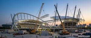
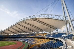
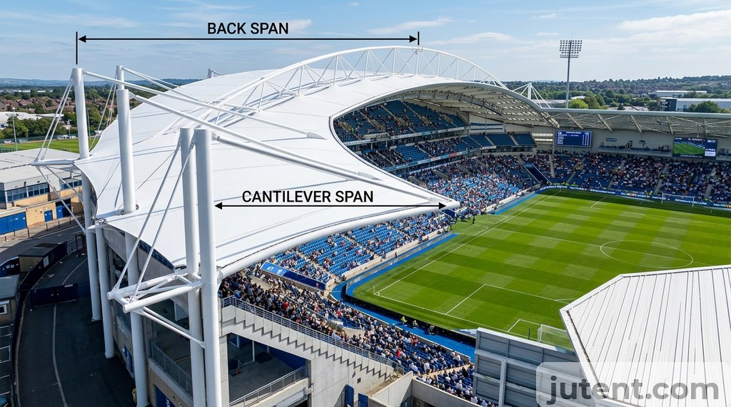
L'avantage principal d'un porte-à-faux canopy de grandstand est l'élimination des poteaux avant. Ces poteaux, bien qu'efficaces structurellement, obstruent les lignes de vue des spectateurs, diminuant l'expérience visuelle et pouvant enfreindre les normes de conception des lieux. En transférant toutes les charges structurelles aux poteaux positionnés derrière la zone d'assise, une conception en porte-à-faux garantit une vue dégagée sur l'ensemble de la tribune. Cette capacité de portée libre est primordiale pour les stades sportifs, les salles de concert et les espaces de rassemblement public où la clarté visuelle est non négociable.
Cependant, cet avantage architectural introduit des défis structurels spécifiques. L'ensemble de la charge de l'auvent, y compris son poids propre, les charges de neige et surtout le soulèvement dû au vent, doit être résisté par une liaison de moment au niveau des poteaux arrière et de leurs fondations. Cela nécessite des éléments structurels plus grands et plus rigides ainsi que des systèmes de fondation robustes par rapport à un toit soutenu par des poteaux. Pour des profondeurs d'assise de tribune typiques allant de 10 m à 20 m, un porte-à-faux est souvent la solution la plus élégante, à condition que les implications structurelles soient comprises dès le début de la phase de conception.
Limites de portée : Jusqu'où un auvent de tribune en porte-à-faux peut-il atteindre ?
Bien que théoriquement illimitée, la portée pratique et économique d'un pur cantilever canopy de grandstand atteint généralement son maximum entre 20 m et 25 m. Au-delà de cette plage, le coût structurel augmente fortement. Le principal moteur de cette augmentation des coûts est la croissance exponentielle de la taille et du poids des poutres principales du cantilever nécessaires pour résister aux moments de flexion et maintenir une flèche acceptable. Par exemple, étendre un cantilever de 18 m à 25 m peut nécessiter une augmentation de la hauteur de la poutre principale de 30 à 50 % et une augmentation correspondante de l'épaisseur des semelles et de l'âme. Cela se traduit directement par des sections d'acier plus lourdes, une fabrication plus complexe et des fondations significativement plus grandes pour contrer les moments de renversement accrus.
Pour un porte-à-faux de 15 m, une poutre primaire typique pourrait être une poutre en I de 600x300 mm. En poussant jusqu'à 25 m, cela pourrait nécessiter une section de 1000x500 mm ou même une poutre treillis, le tonnage d'acier augmentant de manière disproportionnée par rapport à l'extension de la portée. Cette augmentation rapide de la complexité des matériaux et de la fabrication rend les formes structurelles alternatives plus viables pour les portées dépassant 25 m.
Canopy de grandstand Guide des structures
Rapport de portée arrière : le principe d'ingénierie qui détermine l'emplacement des colonnes
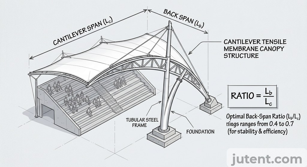
Le rapport de porte-à-faux définit la relation entre la portée avant d'un cantilever et la structure s'étendant derrière ses piliers de support principaux (porte-à-faux arrière). Ce porte-à-faux arrière agit comme un contrepoids, utilisant la gravité et sa connexion aux piliers arrière pour résister au moment de renversement du cantilever. Pour une efficacité structurelle, un rapport de porte-à-faux optimal se situe généralement entre 1:1 et 1:2 (porte-à-faux arrière par rapport à la portée avant).
Une portée arrière plus longue réduit les efforts de traction sur les poteaux de la portée arrière et les efforts de soulèvement sur leurs fondations. Par exemple, un porte-à-faux de 15 m avec un rapport de portée arrière de 1:1 (portée arrière de 15 m) génère un soulèvement de fondation nettement inférieur à celui du même porte-à-faux avec un rapport de 1:0,5 (portée arrière de 7,5 m). Une portée arrière plus courte augmente l'effort de soulèvement supporté par la fondation, nécessitant souvent des pieux profonds ou des blocs de béton massifs. À l'inverse, une portée arrière plus longue permet une utilisation plus efficace des matériaux et des conceptions de fondations plus simples, mais nécessite un espace disponible derrière la tribune. Pour un porte-à-faux de 20 m, un rapport de portée arrière de 1:1 (portée arrière de 20 m) pourrait nécessiter un bloc de fondation de 4 m x 4 m x 3 m de profondeur pour résister au renversement et au soulèvement dans une zone de vent modérée.
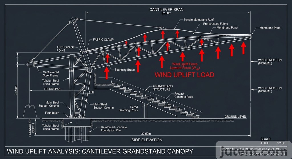
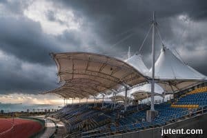
Soulèvement dû au vent : le cas de charge critique pour les structures de gradins en cantilever
Pour les auvents de tribunes en porte-à-faux, la sous-pression due au vent est la charge de conception critique, dictant souvent le dimensionnement des éléments structurels et la conception des fondations. Elle crée une aspiration sur la surface de l'auvent, générant des charges de traction importantes dans les poteaux de retombée et des forces de soulèvement substantielles sur leurs fondations. L'ampleur de la sous-pression due au vent dépend de la zone de vent locale, de la géométrie de l'auvent (pente, conditions de bord) et de l'exposition.
Les ingénieurs calculent ces forces de soulèvement en se basant sur les codes du bâtiment pertinents (par exemple, ASCE 7, Eurocode, NSCP). Par exemple, dans une zone de vents forts avec une vitesse de vent de conception de 200 km/h (environ 55 m/s), les pressions de soulèvement peuvent dépasser 2 kPa (200 kg/m²) sur la toiture. Cela se traduit par des centaines de kilonewtons de force de soulèvement nécessitant un ancrage. Un projet de terrain de basket-ball aux Philippines, soumis à une charge de vent de 250 km/h selon le NSCP, a nécessité des poteaux primaires SHS de 150×150×6 mm avec des plaques de base à connexion par moment. L'identification précoce de ce besoin a évité au projet une réingénierie après la soumission du permis. Cela nécessite des connexions robustes, des sections d'acier primaire lourdes et des fondations profondes, souvent sur pieux, conçues pour résister à une tension significative. Sous-estimer le soulèvement dû au vent risque une défaillance structurelle catastrophique.
Quand passer du cantilever aux formes haubanées ou arquées
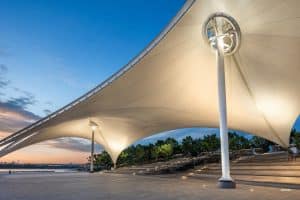
Les auvents de gradins cantilever deviennent économiquement et pratiquement limités au-delà de portées de 20 à 25 m. Lorsque les exigences du projet dépassent ce seuil, ou qu'une esthétique plus légère est souhaitée, les structures membranaires tendues à haubans ou en arc offrent des alternatives plus efficaces.
Structures haubanées : Pour les portées dépassant 25 m, les conceptions haubanées offrent une efficacité structurelle supérieure. Les câbles tendus depuis un mât ou un pylône transforment une partie importante du moment de flexion dans la poutre principale en tension axiale. Cela permet d'utiliser des éléments en acier primaire plus légers ; par exemple, une poutre en porte-à-faux de 1000x500 mm pourrait être remplacée par un équivalent haubané de 600x300 mm pour la même portée. Le compromis implique une complexité accrue dans la fabrication, le montage, les raccords d'extrémité de câbles spécialisés et les procédures de mise en tension.
Formes en arche : Les structures arquées, souvent dotées de membranes tendues, tirent leur résistance de leur géométrie, transférant les charges principalement par compression. Cela réduit les moments de flexion dans les éléments principaux, les rendant efficaces pour de très longues portées ou des déclarations architecturales distinctives. Cependant, les arches nécessitent un contreventement latéral important ou des supports d'extrémité robustes pour résister aux forces de poussée, et leur fabrication est plus complexe que celle des poutres standard. Les deux formes optimisent l'utilisation des matériaux et l'expression esthétique pour des applications de tribunes à longue portée exigeantes.
Demandes de modèles 3D et de dessins : ce que Jutent peut fournir avant commande
Pour les structures complexes comme les auvents de gradins en porte-à-faux, visualiser la conception et coordonner avec les autres corps de métier est crucial. Jutent comprend ce besoin et fournit un accompagnement complet avant même qu'une commande ne soit passée. Pour les demandes de projets sérieuses, nous proposons des modèles 3D préliminaires dans des formats courants tels que SketchUp (SKP) ou STEP (STP). Ces modèles permettent aux ingénieurs en structure et aux entrepreneurs d'intégrer la conception de l'auvent dans leurs modèles de projet globaux, de vérifier les interférences, de valider les dégagements et de présenter une représentation visuelle claire aux parties prenantes.
Ces modèles préliminaires sont généralement fournis dans un délai de 5 à 7 jours ouvrables après réception des exigences détaillées du projet, y compris la profondeur des gradins, la portée souhaitée et la zone de vent. Bien que ces modèles soient destinés à la visualisation et à la coordination, ils sont basés sur nos principes d'ingénierie établis. Des dessins structurels détaillés complets, incluant les détails de connexion, les charges de fondation et les spécifications de fabrication, sont fournis après confirmation de la commande, garantissant que la conception finale est entièrement calculée et prête pour la construction. Dans un récent projet de terrain de padel à Dubaï, le client avait besoin d'une portée libre de 44 m × 22 m sans piliers intermédiaires — une configuration qui nécessitait un système primaire contreventé par câbles plutôt qu'un portique standard. Les dessins d'ingénierie ont été réalisés en 12 jours. Cette approche par étapes garantit que les clients disposent des informations nécessaires pour la planification préliminaire sans s'engager dans une conception complète tant que le projet n'est pas confirmé.
FAQ
- Quelle est la portée maximale pratique d'un cantilever pour canopy de grandstand?
- Pour la plupart canopy de grandstand projets, une limite de portée pratique pour un cantilever se situe entre 20 et 25 mètres. Dépasser cette plage nécessite généralement une structure de contre-portée beaucoup plus lourde et complexe, entraînant des augmentations substantielles des coûts de matériaux et de fabrication. Au-delà de 25 mètres, l'efficacité structurelle d'une conception en pur cantilever diminue considérablement, faisant des systèmes de membrane tendue haubanés une solution plus viable structurellement et économiquement pour atteindre de plus grandes portées sans encourir de dépenses disproportionnées.
- Jutent fournit-elle des modèles 3D pour les projets d'auvent de tribune en porte-à-faux ?
- Oui, pour les demandes de projets sérieuses, nous fournissons des modèles 3D préliminaires d'auvents de tribune en porte-à-faux. Ces modèles sont généralement livrés au format SKP ou STP, permettant à votre équipe de conception de les intégrer de manière transparente dans vos visualisations globales du projet et d'effectuer une détection initiale des collisions. Cette modélisation en phase précoce aide à comprendre les exigences spatiales et l'intégration esthétique. Des dessins structurels complets, incluant des conceptions de connexions détaillées et des spécifications de matériaux, sont ensuite fournis après confirmation de la commande, garantissant que toutes les informations nécessaires sont disponibles pour la fabrication et l'installation.
Envoyez-nous la profondeur de vos gradins et votre zone de vent, et nous vous fournirons une recommandation de portée en cantilever avec un coût indicatif.