Specifying a bus station canopy involves five decisions that most contractors and transit developers get wrong the first time: structural form, membrane grade, wind load compliance, clearance height, and foundation sizing. This guide covers each one, with the exact numbers and engineering parameters you need to get the specification right before you go to tender.
What Makes Bus Station Canopy Specification Different
Transit environments impose strict physical and chemical demands that standard commercial shade structures never encounter. A bus station canopy must accommodate dynamic vehicle envelopes, manage high-density pedestrian flow, and withstand constant exposure to diesel exhaust particulates. These three factors dictate every subsequent engineering decision, from column placement to membrane selection.
The most critical geometric constraint is vertical clearance. A standard city bus requires a minimum vertical clearance of 4.5m. If the transit hub services double-decker or articulated routes, the required clearance increases to 5.5m or 6.0m. Elevating the roofline to these heights drastically alters the wind uplift calculations compared to a standard 3m pedestrian walkway cover. The primary steel framework must be upsized to handle the increased overturning moments at the base plates.
Chemical exposure is the second major differentiator. The constant idling of diesel engines deposits carbon particulates and unburned hydrocarbons directly onto the underside and edges of the canopy. If a low-grade PVC membrane is specified, this soot bonds chemically to the plasticizers in the fabric, permanently discoloring the structure within 18 to 24 months. Specifying a 1050g/㎡ PVDF membrane with a high-density fluorocarbon topcoat prevents this bonding. The PVDF layer acts as a chemical barrier, allowing rain or standard low-pressure washing to clear the surface and maintain light transmission.
Finally, transit canopies require heavy integration of secondary systems. Lighting, CCTV cameras, and public address speakers must be mounted directly to the primary steelwork. This requires pre-drilled mounting plates and concealed conduit routing within the structural columns to prevent vandalism and weather exposure. When specifying Transit Canopies, the engineering drawings must account for the dead load of these secondary systems and provide designated access panels for maintenance crews.
Structural Forms: Tensile, Hip Roof, and Modular Canopy Options
Selecting the correct structural geometry determines the steel tonnage, the foundation footprint, and the overall project budget. Transit authorities typically rely on three primary configurations, each suited to specific platform layouts and span requirements.
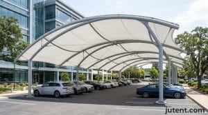
Tensile membrane structures, utilizing conic or hyperbolic paraboloid (hypar) geometries, handle the largest clear spans. A conic tensile structure can easily achieve a 20m to 30m clear span with a single central mast. This configuration is highly efficient for wide, central island platforms where perimeter columns would obstruct passenger boarding zones. The double-curvature of the membrane provides exceptional structural stability under wind load, transferring forces efficiently to the perimeter catenary cables and tie-downs.
Hip roof structures provide a more traditional, linear coverage profile. These are typically supported by a series of portal frames spaced at 6m to 8m intervals. The hip roof geometry sheds water predictably to the perimeter, making it easier to integrate standard guttering and downpipe systems. This form requires more steel columns per square meter than a tensile conic structure, but the individual steel members are smaller, often utilizing 150×150×6mm or 200×200×8mm Square Hollow Sections (SHS).
Modular cantilever canopies are the standard for curbside applications. These systems utilize a single row of rear columns with projecting cantilever arms. The primary advantage is the complete elimination of columns near the vehicle approach lane.
| Structural Form | Optimal Clear Span | Steel Tonnage (kg/㎡) | Best Transit Application |
|---|---|---|---|
| Tensile Conic | 15m – 30m | 25 – 35 | Large island platforms, main concourses |
| Linear Hip Roof | 6m – 12m | 35 – 45 | Long, straight boarding platforms |
| Modular Cantilever | 3m – 6m | 40 – 55 | Curbside stops, narrow sidewalks |
When evaluating these forms, the choice of membrane material is equally critical. For a detailed technical breakdown of material lifespans and tensile strengths across these geometries, review our Pvdf Vs Ptfe Membrane Comparison.
Wind Load and Structural Compliance for Transit Facilities
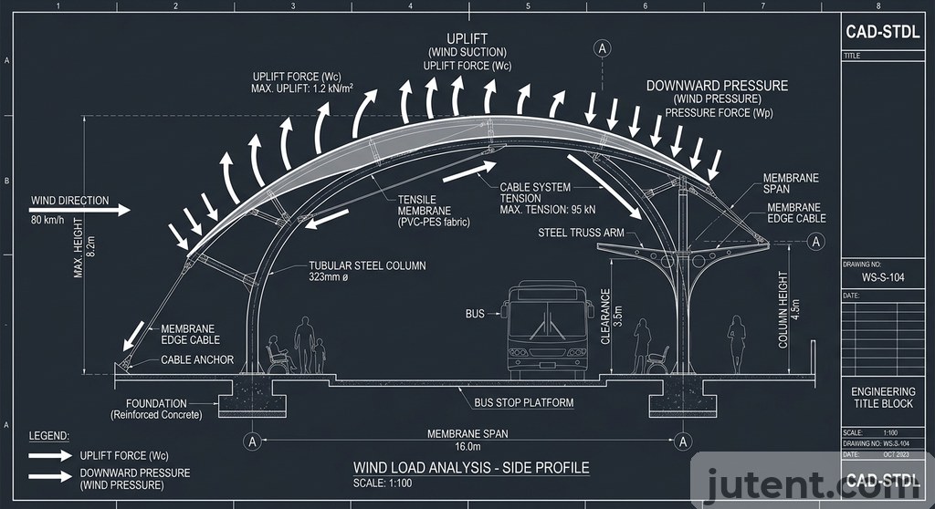
Wind loading dictates the primary steel sizing and foundation engineering for any transit canopy. Because bus station canopies are essentially large, open-sided airfoils elevated 5m above the ground, they are subjected to severe uplift forces. Downward dead loads are minimal; the engineering challenge is entirely about preventing the structure from tearing off its footings during a storm event.
For export projects in high-wind or high-exposure regions, the structure should be engineered to the applicable local code and checked against the project-specific loading conditions.
Structural compliance requires adherence to local wind codes, typically ASCE 7-16, Eurocode 1, or regional equivalents. The engineering model must account for both positive pressure (wind pushing down on the membrane) and negative pressure (wind pulling up). In a 150km/h wind zone, the uplift force on a 10m × 10m canopy section can exceed 120 kilonewtons.
To resist these forces, the membrane must be pre-stressed to exact specifications. The fabric is tensioned using threaded perimeter studs or adjustable membrane plates until it reaches a pre-stress level of approximately 2.5 to 3.0 kN/m. This tension prevents the membrane from fluttering. Wind flutter is the primary cause of premature failure in tensile structures; it causes fatigue in the steel connections and micro-cracking in the membrane coating. Proper engineering ensures the natural frequency of the tensioned membrane remains higher than the frequency of the design wind gusts, eliminating destructive resonance.
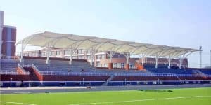
Bus Terminal Canopy: Large-Scale Transit Hub Requirements
A bus terminal canopy differs from a standard transit shelter primarily in structural scale, wind uplift resistance, and water management. These structures often cover multiple boarding lanes, pedestrian concourses, and ticketing areas, requiring continuous coverage footprints exceeding 2,000 square meters. At this scale, the engineering focus shifts from simple cantilevered frames to long-span primary steelwork and high-volume, integrated drainage systems.
To span three bus lanes and two passenger platforms simultaneously, a terminal canopy typically requires a clear span of 30 to 40 meters. Standard rolled steel sections become too heavy and structurally inefficient for these distances. Instead, the primary structure utilizes fabricated steel trusses or cable-stayed masts using Q355B high-strength structural steel. A three-dimensional space frame or a deep planar truss—typically 1.2 to 1.5 meters deep—can span 35 meters while maintaining a low dead weight. This reduces the required foundation size, lowering excavation costs and minimizing disruption to underground transit utilities during construction.
Water management presents a strict safety and operational requirement at the terminal scale. A 2,000-square-meter canopy collects approximately 100,000 liters of water during a 50mm rain event. Allowing this volume to shed off the perimeter onto boarding buses or pedestrian walkways creates slip hazards and operational delays. Terminal canopies require integrated, high-capacity internal drainage.
The tensile membrane is precisely patterned to direct water toward central collection points, typically located at the primary support columns. Water enters stainless steel sump boxes equipped with debris guards and is routed down through the center of the structural columns via 150mm or 200mm UPVC downpipes. For massive terminal roofs, engineers specify siphonic drainage systems. Unlike standard gravity drainage, siphonic systems operate at full capacity with negative pressure and no air in the pipes. This allows contractors to use smaller pipe diameters and route pipes horizontally within the steel trusses for up to 20 meters before dropping to the underground stormwater network, preserving maximum vertical clearance for double-decker buses.
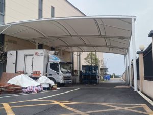
Bus Stop Tensile Structure: Smaller-Scale Applications
For individual curbside boarding locations, the bus stop tensile structure provides high-performance weather protection within a highly constrained footprint. The defining characteristic of a curbside stop is the need to keep the structural columns strictly away from the vehicle approach path to prevent collision damage from bus mirrors and tail swings.
This constraint makes the cantilever geometry mandatory. A standard bus stop tensile structure utilizes a rear-aligned column row set back at least 1.5m from the curb line. The canopy roof projects forward 2.5m to 3.5m to cover the waiting area and the boarding threshold.
Because the entire roof load is suspended on one side of the column, the structure generates a massive overturning moment at the foundation. To counteract this, the primary columns (typically 114mm or 140mm Circular Hollow Sections) are anchored to heavy, offset concrete pad footings. A typical footing for a 3m cantilever stop in a standard wind zone might measure 1.5m × 1.5m × 0.8m deep, acting as a dead-weight counter-balance to the cantilever arm.
The membrane specification for these smaller structures remains rigorous. While the spans are shorter, the proximity to the roadway means the fabric is subjected to concentrated exhaust fumes and road spray. A 900g/㎡ or 1050g/㎡ PVDF membrane is required to maintain a clean appearance. The fabric is typically tensioned using a perimeter aluminum extrusion system, which allows for a crisp, low-profile edge detail that fits well within urban streetscapes. Installation of these modular units is highly efficient; a trained crew can typically erect a pre-assembled double-bay bus stop structure in a single working day.
Bus Station Canopy Cost: What Drives the Budget
Budget planning should be based on structure type, clear span, wind rating, membrane grade, steel tonnage, and project scope. For an accurate EXW, FOB, CIP, or DDU quotation, the project dimensions and engineering requirements should be reviewed first.
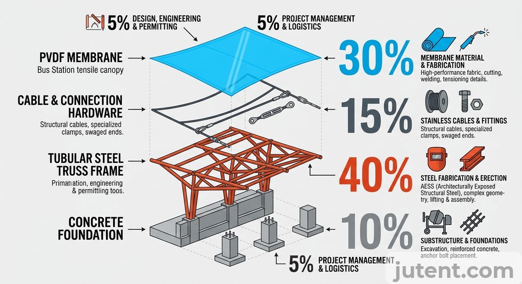
Steel tonnage is the primary cost driver. The membrane itself, even a premium 1050g/㎡ PVDF, only accounts for 15% to 25% of the total material cost. The heavy steel required to meet wind loads and achieve long clear spans consumes the majority of the budget. A standard modular bus stop might require 35kg of steel per square meter of coverage. A 30m clear-span terminal canopy engineered for a 200km/h wind zone might require 65kg of steel per square meter. Every additional kilogram of steel increases the raw material cost, the fabrication time, and the shipping weight.
Surface treatment should be selected according to the project’s corrosion-resistance target and lifecycle requirements rather than a fixed published add-on cost.
Economy of scale also heavily influences the per-square-meter rate. The engineering, patterning, and machine-setup costs are relatively fixed. Spreading these fixed costs over a 2,000㎡ terminal canopy results in a highly efficient per-square-meter price. Conversely, ordering a single 15㎡ bus stop will push the unit rate toward the absolute top of the pricing spectrum.
What Jutent Provides: Factory Supply, Documentation, and Logistics
Procuring a bus station canopy requires a manufacturing partner capable of delivering precision-engineered components that assemble flawlessly on site. Field welding and site modifications are strictly prohibited in modern transit construction due to safety regulations and the risk of compromising the hot-dip galvanized steel coating. Contractors need predictable, bolt-together systems to maintain project schedules and control labor costs.
hot-dip galvanizing or another corrosion-protection system specified for the project, subject to project design
For export projects in high-wind or high-exposure regions, the structure should be engineered to the applicable local code and checked against the project-specific loading conditions.
A 40GP container typically supports about 21–28 tons of payload, while the actual covered area depends on structure type, steel quantity, and packing method.
Alongside the physical materials, Jutent provides the exact documentation package required for municipal handover. This includes general arrangement drawings, foundation reaction loads for the civil engineer of record, material test certificates for steel and fabric, membrane tensioning sequences, and long-term maintenance schedules. This data package allows contractors to pass final structural inspections without delay.
If you want an accurate budget reference for this project, share your dimensions, wind zone, and preferred membrane type with our team.
FAQ
- What structural form is most common for bus station canopies?
- For bus station canopies, the most common structural forms are hip roof and tensile canopy designs. Hip roofs offer robust protection and are often selected for their traditional aesthetic and straightforward construction, particularly for smaller to medium spans. Tensile canopy structures, conversely, provide greater design flexibility and can efficiently cover larger spans with fewer internal supports, which is advantageous in high-traffic areas requiring unobstructed pedestrian flow. The choice between these forms largely depends on the required span, site-specific wind loads, desired visual impact, and budget considerations.
- What is the typical lead time for a bus station canopy from Jutent?
- For a typical bus station canopy, the factory production phase generally takes between 25 and 40 days, depending on the complexity of the structural form and the specific membrane grade selected. Following production, sea freight to Southeast Asian destinations usually requires an additional 7 to 14 days for transit. Therefore, project managers and procurement teams should anticipate a total lead time of approximately 6 to 9 weeks from order confirmation to the arrival of the canopy components at the port of destination. This timeframe allows for meticulous fabrication and efficient logistics planning.