Specifying a toll station canopy involves five decisions that most contractors get wrong the first time: structural form, clearance heights, wind load compliance, membrane grade, and procurement logistics. This guide covers each one, with the numbers you need to get the specification right before you go to tender.
What Makes Toll Station Canopy Specification Different
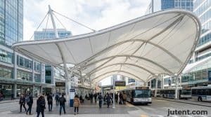
A toll plaza operates in one of the most aggressive environments possible for a lightweight structure. The canopy must provide continuous weather protection for toll operators and sensitive electronic equipment while withstanding constant exposure to diesel exhaust, brake dust, and high-velocity crosswinds generated by heavy goods vehicles (HGVs). Standard commercial shade structures fail rapidly under these conditions because they are not engineered for the continuous aerodynamic buffeting and chemical exposure inherent to highway infrastructure.
The primary constraint in toll station design is the foundation footprint. The structure must be anchored to narrow concrete traffic islands, which are typically only 1.2m to 2.0m wide. These islands already house toll booths, automatic number plate recognition (ANPR) camera masts, and impact barriers. This leaves minimal space for structural columns and base plates, forcing engineers to utilize heavy-wall steel profiles that can handle high bending moments on a restricted base. To prevent fatigue failure from constant HGV slipstream vibrations, the column-to-baseplate connections require rigid moment-resisting designs rather than standard pinned joints.
Based on Jutent’s experience across 400+ projects in 30+ countries, similar specification issues often appear when early-stage assumptions are made before the engineering conditions are confirmed.
Corrosion protection and service life should be described according to the selected protection system, project environment, and maintenance conditions rather than as an unconditional lifespan guarantee.
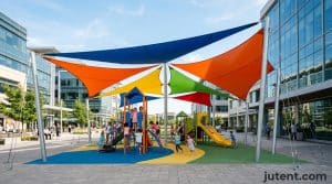
Structural Forms: Cantilever and Tensile Options for Toll Plazas
The geometry of the toll plaza dictates the structural form. Engineers must choose between island-supported cantilever systems and perimeter-supported clear-span tensile structures. Each approach fundamentally changes the steel tonnage and foundation requirements of the project.
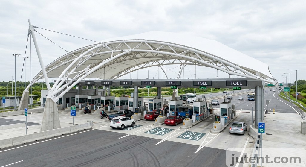
The double-sided cantilever, often designed as a gull-wing or umbrella form, is the most common configuration for multi-lane plazas. A single row of primary columns is anchored to the central traffic islands, with steel arms projecting outward over the adjacent lanes. This design minimizes the total structural footprint and allows for modular expansion if new lanes are added. However, because the entire roof load is supported by a single column line, the base plates must resist massive overturning moments. A typical cantilever column for a 12m roof span requires an 800mm × 800mm × 30mm steel base plate secured with eight M30 anchor bolts.
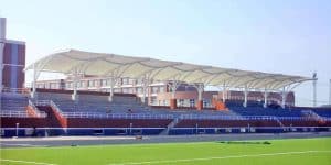
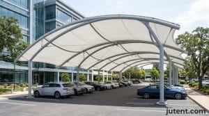
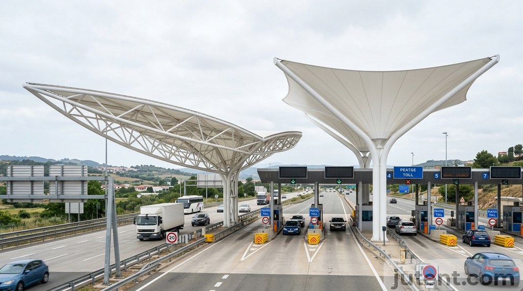
A clear-span toll plaza tensile structure takes the opposite approach. Instead of placing columns on the narrow traffic islands, massive primary masts are positioned at the extreme outer edges of the highway. A network of steel cables and architectural membrane is then tensioned across the entire plaza, creating a single uninterrupted roof that can span 40m or more. This removes all structural columns from the vehicle impact zone and provides total freedom for lane reconfiguration.
The trade-off for a clear-span design is the foundation requirement at the perimeter. The tension loads transferred to the outer masts require deep pile foundations or massive concrete deadmen to resist the lateral pull of the cables. For most regional highway projects, the modular cantilever system provides a more predictable installation path, while the clear-span approach is reserved for high-profile architectural gateways. Pvdf Vs Ptfe Membrane Comparison
Clearance Requirements: Vehicle Height and Lane Width Considerations
Clearance geometry determines both the structural height and the required roof overhang. A toll canopy must allow the tallest legal vehicles to pass safely while still providing effective rain shadows for the toll operators sitting at a much lower elevation.
Standard vehicle lanes are typically designed at 3.0m to 3.2m wide, while oversized HGV lanes require 3.5m to 4.0m of width. The legal maximum vehicle height in most jurisdictions ranges from 4.5m to 4.8m. To prevent catastrophic impacts from bouncing trailers or unsecured loads, the absolute minimum structural soffit height (the lowest point of the steel frame or membrane) is strictly set at 5.5m. This 5.5m baseline also provides the necessary vertical space to mount lane control signals, clearance bars, and ANPR camera housings beneath the roof line.
This extreme height creates a specific weather protection challenge. A toll operator sits in a booth with a transaction window located approximately 1.2m above the ground. If the roof is 5.5m high, wind-driven rain can easily bypass the canopy and flood the booth window. To solve this, the canopy must project significantly beyond the edge of the toll booth.
The standard engineering rule for high-clearance canopies is a 45-degree weather protection angle. To protect a 1.2m-high window from a 5.5m-high roof, the canopy edge must extend horizontally at least 4.3m from the face of the booth. If the traffic island is 2.0m wide, the total roof width per lane must be carefully calculated to ensure the overhangs from adjacent islands meet in the center of the lane, creating a continuous dry zone across the entire plaza width.
Wind Load and Structural Compliance for Toll Facilities
Toll plazas are almost exclusively located in open terrain—classified in engineering codes as Exposure Category C or D. Without surrounding buildings to break the airflow, the canopy is subjected to the full force of regional wind events. The open-sided nature of the structure creates severe aerodynamic challenges.
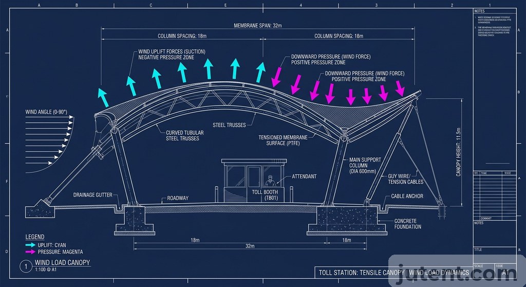
When high-velocity wind strikes a solid building, it flows around it. When wind strikes an open toll canopy, it flows under it, creating massive positive uplift pressure on the underside of the membrane while simultaneously creating negative suction on the top surface. The combined uplift coefficient on a flat or low-pitch canopy can exceed 1.2. For a standard 6-lane toll plaza with a 600-square-meter roof area, a 140km/h wind event can generate over 450kN of vertical uplift force.
In a recent highway toll plaza project in Southeast Asia, the client required the structure to meet a 180km/h typhoon wind loading. We specified 500mm × 500mm × 16mm Square Hollow Section (SHS) primary columns manufactured from Q355B high-yield steel, combined with moment-connected base plates. Catching this requirement at the design stage saved the project a complete re-engineering cycle after permit submission.
To manage these forces, the membrane must be engineered with deep anticlastic curvature (a saddle shape). Flat membranes flutter under wind loads, which causes the fabric to fatigue and tear at the connection plates. By introducing a minimum of 10% curvature into the design, the membrane remains under constant bi-axial tension. This pre-stress locks the fabric in place, transferring the wind loads directly into the steel boundary cables and down through the primary columns, ensuring the structure remains rigid and silent even during severe storm events.
Gas Station Tensile Canopy: Fuel Station Applications
The engineering principles used for toll plazas translate directly to fuel retail environments. A gas station tensile canopy or petrol station canopy shares the exact same requirements for high HGV clearance, wide column spacing, and open-terrain wind resistance. However, fuel station applications introduce strict regulatory constraints regarding fire safety and underground infrastructure.
The primary constraint for a fuel station canopy is the location of the Underground Storage Tanks (USTs) and the associated fuel line trenches. Structural columns cannot be placed over or near these zones. This often forces the canopy design into asymmetrical cantilever configurations or wide-span portal frames to bridge over the fueling infrastructure. The base plate engineering must account for these eccentric loads while ensuring the anchor bolts do not interfere with subterranean vapor recovery lines.
Fire compliance dictates the material specification. A fuel station canopy operates directly above highly flammable liquid dispensers. The architectural membrane must meet strict non-combustible or flame-retardant standards. For these applications, the membrane must achieve a Class B1 (DIN 4102) or Class A2 fire rating. If a fire occurs at the pump, the membrane is designed to melt and vent the heat upward, rather than propagating the flame across the roof structure or dropping flaming debris onto the vehicles below.
Lighting integration is the final critical difference. While toll plazas require general area illumination, a petrol station canopy must deliver highly targeted lighting to the pump islands—typically requiring 300 to 500 lux at the dispenser face to ensure safe operation and high retail visibility. The tensile structure must be designed with integrated steel mounting nodes welded directly to the primary frame, allowing heavy LED canopy luminaires to be suspended securely without penetrating or chafing the tensioned membrane.
Toll Station Canopy Cost: What Drives the Budget
Budget planning should be based on structure type, clear span, wind rating, membrane grade, steel tonnage, and project scope. For an accurate EXW, FOB, CIP, or DDU quotation, the project dimensions and engineering requirements should be reviewed first.
The steel framework accounts for 55% to 65% of the total material cost. As the clear span of the canopy increases, the required steel weight increases exponentially, not linearly. A standard modular cantilever canopy spanning 12m might require 35kg of steel per square meter of roof area. A clear-span tensile structure spanning 40m across multiple lanes will require massive perimeter masts and heavy-wall trusses, pushing the steel requirement to 65kg or 70kg per square meter.
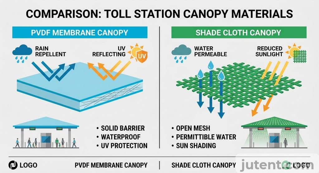
The architectural membrane accounts for 20% to 25% of the cost. Upgrading from a standard 900g/㎡ architectural fabric to a heavy-duty 1050g/㎡ PVDF membrane adds approximately $4 to $6 per square meter. Given the extreme cost of closing a toll lane to replace a degraded roof five years later, specifying the heavier, self-cleaning 1050g/㎡ grade is a mandatory investment for highway infrastructure.
Company experience should be described through verified export experience and project support capability rather than unsupported project anecdotes.
What Jutent Provides: Factory Supply, Documentation, and Logistics
Jutent operates as a specialized toll station canopy manufacturer, delivering a complete pre-engineered structural kit directly to the project site. We manage the structural engineering, steel fabrication, membrane patterning, and international logistics. The local main contractor assumes responsibility for pouring the concrete foundations and executing the mechanical assembly.
The supply scope begins with comprehensive engineering documentation. We provide the contractor with exact foundation reaction forces—detailing maximum vertical loads, horizontal shear, and overturning moments under peak wind and snow conditions. This data allows the local civil engineer to design the concrete footings accurately. We also supply the complete set of structural shop drawings, membrane tensioning sequences, and a step-by-step mechanical installation manual featuring 3D rigging diagrams.
hot-dip galvanizing or another corrosion-protection system specified for the project, subject to project design
Logistics are engineered for standard global shipping infrastructure. The steel columns, roof trusses, and rolled membrane bundles are dimensioned specifically to fit inside standard 40-foot Open Top (OT) or 40-foot High Cube (HC) shipping containers. Components are secured on custom steel pallets with designated lifting points to prevent transit damage and facilitate safe unloading. By pre-fabricating all structural connections in the factory, we eliminate the requirement for site welding. The local contractor unloads the containers, bolts the steel frame together using the supplied Grade 8.8 or 10.9 high-tensile galvanized hardware, and tensions the membrane using the integrated perimeter clamping plates.
If you want an accurate budget reference for this project, share your dimensions, wind zone, and preferred membrane type with our team.
FAQ
- What is the typical lead time for a toll station canopy from Jutent?
- Factory production: 20–35 days. Sea freight to Southeast Asia: 7–14 days. Total: 5–8 weeks. *Engineering Context:* The 20-to-35-day factory production window begins after the final shop drawings are approved by the client. This timeline includes the procurement of Q355B structural steel, CNC cutting, automated welding, and the mandatory 85-micron hot-dip galvanizing process. The membrane patterning and high-frequency welding occur concurrently in our climate-controlled textile facility. Because all components are pre-engineered to bolt together without site welding, the structure is test-fitted in the factory before being packed into 40ft High Cube containers for immediate dispatch to the port.
- What membrane grade is recommended for a toll station canopy?
- High-grade PVDF membrane is recommended for most commercial applications. *Engineering Context:* For highway and toll plaza environments, we specifically mandate a 1050g/㎡ architectural membrane coated with a high-concentration Polyvinylidene Fluoride (PVDF) lacquer. The 1050g/㎡ weight provides the necessary tensile strength to resist 140km/h+ wind uplift forces without fatiguing. More importantly, the PVDF topcoat provides a low-friction, self-cleaning surface. In a toll station environment heavily polluted by unburned diesel particulates and brake dust, a standard PVC membrane will permanently discolor within two years. The PVDF coating ensures that UV radiation is reflected and that rainwater effectively washes the exhaust particulates off the canopy, maintaining the structure’s visual appearance and light transmission for a 15-to-20-year design life.