Wind load is the critical structural consideration for bus station canopies — not just for safety, but for authority approval. Understanding how wind load is calculated and what standards apply is essential before specifying.
Why Wind Load Matters More Than You Think for Bus Station Canopies
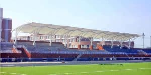
For structural engineers and contractors involved in transit infrastructure, the design of a bus station canopy often appears straightforward. However, the seemingly simple task of providing shelter for commuters belies one of the most complex and critical engineering challenges: wind load. Unlike enclosed buildings, canopies are highly susceptible to aerodynamic forces due to their open nature and large surface areas. These forces don’t just push down; they can create uplift, torsion, and dynamic vibrations that can lead to structural fatigue or catastrophic failure if not properly accounted for. A poorly designed canopy isn’t just a safety hazard; it’s a significant liability that can halt a project during the approval phase. Authorities rigorously scrutinize wind load calculations, demanding adherence to local building codes and international standards. Ignoring this can result in costly redesigns, project delays, and reputational damage. For transit canopies, the stakes are particularly high given their public location and the potential for high-speed winds, including extreme weather events like typhoons. Ensuring structural integrity from the outset is paramount.
Transit Canopies
How Wind Load Is Calculated for Bus Station Canopies
Calculating wind load for bus station canopies involves a multi-faceted approach that considers geographical location, site-specific conditions, and the canopy’s geometry. The fundamental principle is based on Bernoulli’s equation, where wind pressure is proportional to the square of the wind speed. However, real-world application requires far more detail. Key factors include:
- Basic Wind Speed (V): This is the maximum 3-second gust speed at 10 meters above ground in open terrain, with a specific return period (e.g., 50-year or 100-year). This value is typically derived from regional meteorological data and specified in local building codes.
- Terrain Category: The roughness of the surrounding terrain (e.g., open country, suburban, urban) affects how wind speed varies with height and generates turbulence.
- Topographic Factor (Kt): Accounts for increases in wind speed over hills, ridges, or escarpments.
- Shielding Factor (Ks): Considers the reduction in wind speed due to upstream obstructions.
- Aerodynamic Shape Factor (Cp): This is crucial for canopies. It’s a dimensionless coefficient that accounts for the pressure distribution on the canopy’s surfaces (both upward and downward) due to its specific shape, pitch, and orientation relative to the wind. These values are often derived from wind tunnel testing or empirical data in standards.
- Dynamic Response Factor (Cd): For flexible structures like tensile canopies, this factor accounts for dynamic amplification due to wind-induced vibrations.
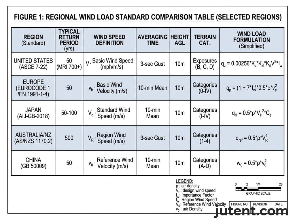
The final design wind pressure (P) is typically calculated using variations of the formula: P = 0.5 * ρ * V^2 * Cd * Cp, where ρ is the air density. Based on Jutent’s experience across 400+ projects in 30+ countries, accurate input data and careful application of these factors are critical for ensuring the structural stability of any transit canopy.
Bus Station Canopy Guide
Regional Standards: AS/NZS, NSCP, SBC, and Other Applicable Codes
Adherence to regional building codes and standards is non-negotiable for bus station canopy projects. These codes dictate the minimum design wind loads, calculation methodologies, and safety factors required for structural integrity and public safety. Key standards include:
- AS/NZS 1170.2 (Australia/New Zealand): This standard specifies the procedures for determining wind actions for structural design. It details terrain categories, shielding factors, topographic multipliers, and aerodynamic shape factors for various building types, including canopies. It’s known for its detailed approach to dynamic response and fatigue for flexible structures.
- NSCP (National Structural Code of the Philippines): The NSCP, particularly Volume 1, Chapter 2, Section 207, outlines the minimum design loads for buildings and other structures, including wind loads. It references ASCE 7 (Minimum Design Loads for Buildings and Other Structures) and adapts it for local conditions, including specific wind zones and typhoon considerations.
- SBC (Saudi Building Code): The SBC, specifically SBC 301 (Structural Loading and Forces), provides thorough guidelines for wind load determination in Saudi Arabia. It aligns closely with international standards like ASCE 7, specifying basic wind speeds, exposure categories, and gust effect factors relevant to the region’s climate.
- Eurocode 1 (EN 1991-1-4): This European standard specifies the actions of wind on structures. It provides methods for calculating characteristic wind speeds, terrain categories, and pressure coefficients for various structural forms, widely used across Europe and in projects seeking international compliance.
- IBC (International Building Code) / ASCE 7 (USA): While the IBC is a model code, it references ASCE 7 for wind load provisions. ASCE 7 is a highly detailed standard that provides extensive guidance on wind speed maps, exposure categories, topographic effects, and pressure coefficients for a wide range of structures, including open buildings and canopies.
Understanding which code applies to a specific project location is the first step. Jutent’s engineering team is proficient in applying these diverse standards to ensure compliance and structural safety for every project.
What Wind Load Data Jutent Provides with Every Transit Project
Jutent Engineering understands that precise wind load data is fundamental for the successful design, approval, and construction of any transit canopy. For every project, we provide a thorough suite of engineering documentation tailored to the specific site and design. This includes:
- Detailed Wind Load Calculations: Our engineers perform meticulous calculations based on the project’s geographical location, local building codes (e.g., AS/NZS, NSCP, SBC, Eurocode, ASCE 7), terrain category, and the specific geometry of the proposed canopy. These calculations determine the design wind pressures for all critical structural elements, including uplift, downward pressure, and lateral forces.
- Structural Analysis Reports: These reports detail how the canopy’s steel framework (Q235B, Q355B) and membrane (1050 g/m² PVDF or PTFE) will respond to the calculated wind loads. This includes stress analysis, deflection analysis, and stability checks, ensuring the structure can withstand extreme conditions without failure.
- Material Specifications: We provide clear specifications for all materials, including the grade of steel, membrane type, and connection hardware (SS304 standard, SS316 optional upgrade), ensuring they meet or exceed the requirements for the determined wind loads. Our surface treatments include epoxy zinc-rich primer + acrylic topcoat, epoxy zinc-rich primer + fluorocarbon topcoat, or hot-dip galvanizing for enhanced durability.
- Design Drawings: Our detailed design drawings visually represent the structural elements, connections, and anchorage points, all designed to safely transfer wind loads to the foundations.
- Installation Manuals: For export projects, Jutent can provide design drawings, calculations, material specifications, installation manuals, and free remote guidance, subject to project scope and contract terms. These manuals include specific instructions for ensuring the structure is erected according to the wind load design.
This thorough documentation package empowers structural engineers and contractors with the necessary information for authority submissions and confident project execution. Typical technical values should always be written conservatively and described as subject to project design.
FAQ
- What wind speed should a bus station canopy be designed for?
- Design wind speed depends heavily on the project’s geographical location and the applicable building code. For instance, in the Philippines, bus station canopies are typically designed for basic wind speeds ranging from 200–250 km/h (as per NSCP, considering typhoon zones). In the UAE, design wind speeds often fall between 45–55 m/s (based on SBC). For Australia and New Zealand, AS/NZS 1170.2 specifies design wind speeds that can range from 41–66 m/s, depending on the wind region and terrain category. These values are basic wind speeds, which are then adjusted for factors like terrain, topography, and structure height to determine the actual design pressure.
- Does Jutent provide stamped wind load calculations for authority submission?
- Jutent Engineering provides detailed engineering calculations and structural analysis reports for all our projects, which form the technical basis for authority submissions. For projects requiring a locally registered engineer’s stamp on these calculations for final authority approval, we collaborate with local registered engineers in the project’s jurisdiction. This ensures that our reliable engineering designs meet both international standards and specific local regulatory requirements, facilitating a smooth approval process for our clients.
Tell us your project location and we’ll provide wind load calculations specific to your region.