Technical Summary: Cable-membrane structures leverage high-strength cable networks and flexible membranes to create lightweight, high-performance spatial surfaces. Unlike rigid structures, these systems depend on form-finding and bi-axial pre-tensioning for stability. This analysis examines their non-linear mechanical response under 150km/h wind loads and the engineering advantages over traditional rigid frames.
Mechanics of Bi-Axial Pre-Tensioning
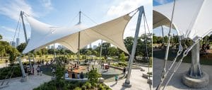
In structural membrane design guidelines, stability is achieved through anticlastic geometry—surfaces with opposing curvatures. By introducing a precise level of pre-stress (typically 2kN/m to 4kN/m), the membrane remains taut under variable environmental loads. This tension prevents mechanical "flutter" and ensures the architectural membrane can withstand standard snow loads of 1.2kN/m² without significant ponding or structural fatigue.
The cable network utilized in these systems typically employs Grade 316 stainless steel or galvanized high-tensile strands. For standard urban or industrial environments, components are specified with a C3-grade corrosion protection coating, providing a durable barrier against atmospheric moisture and oxidation. Computational analysis via non-linear finite element methods (FEM) is required to predict the large-displacement behavior of the system under peak wind pressure.
Technical Comparison: Tensile Systems vs. Conventional Steel
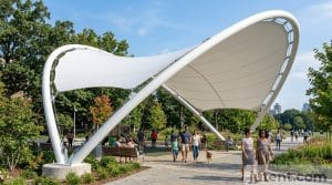
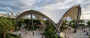
When specifying a fabric roofing system for commercial canopies or large-scale plazas, engineers must weigh the material efficiency against traditional rigid-body construction. The following table highlights the performance benchmarks under identical design criteria (150km/h wind resistance, Seismic Category D):
| Engineering Metric | Cable-Membrane System | Conventional Steel Frame |
|---|---|---|
| Self-Weight Density | 15 - 30 kg/m² | 70 - 130 kg/m² |
| Max Unsupported Span | 100m - 150m+ | 30m - 50m (Standard) |
| Wind Load Response | Damping through deformation | Rigid resistance / Stress concentration |
| Foundation Requirement | Tension-focused (Anchors/Piles) | Compression-focused (Massive Footings) |
| Corrosion Protection | C3 Standard (Medium Durability) | Multi-layer paint / Galvanization |
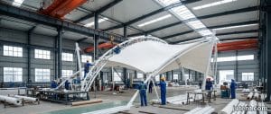
| Installation Timeline | Rapid (Modular Assembly) | Extended (Field Welding/Heavy Lift) |
Anchorage Engineering and Thermal Compensation
The structural integrity of a plaza shading structure or mall entrance canopy depends heavily on its boundary conditions. Force transfer from the membrane to the substructure occurs via catenary cables housed in perimeter pockets. These cables must be engineered to handle high axial forces while maintaining the C3-grade protection standard for urban durability.
Engineering considerations must also account for material creep and thermal expansion. Since membrane structures exhibit non-linear material properties, anchor points often incorporate adjustable threaded terminals. These allow for secondary tensioning post-installation, ensuring the system maintains its calculated equilibrium and drainage slope throughout a service life that can exceed 25 years with high-grade PTFE or PVC/PVDF composites.
Request Technical Specs